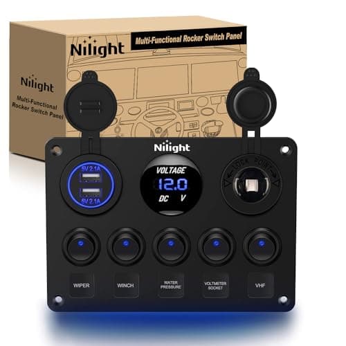
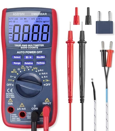
I wired the LED lighting and switch panel on my own 4Runner. Not a kit with a plug on each end — actual relays, an actual fuse block, my own crimps, my own routing, my own mistakes. That is the one piece of first-hand authority I have to offer on this site, and it is worth exactly what it is worth: I know where this job goes wrong, because I got some of it wrong.
Here is the pattern. The accessory almost never fails. What fails is the twelve volts between it and the battery, and it fails for three reasons that are entirely preventable.
The three failures, in the order they happen
1. The wire was too thin
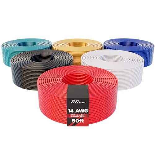
Wire gauge is a number, not a vibe. PowerStream's widely cited AWG table gives 32 amps for 14 AWG copper in chassis wiring, 22 amps for 16 AWG and 16 amps for 18 AWG — and the same table is explicit that these are a rule of thumb for short chassis runs, not a code figure. Anything that needs to conform to a code follows the code.
Two things follow from that. First, look up what your accessory actually draws instead of guessing from its size — a light bar and a compressor are wildly different loads in the same size box. Second, on a long run, size up. Past a few feet, voltage drop rather than heat is what limits you, and the symptom is a dim light or a compressor that struggles at the end of a thin wire.
2. There was no fuse, or it was in the wrong place
The fuse protects the wire, not the accessory. That single sentence fixes most people's intuition about where it goes: as close to the power source as you can practically get it, because everything upstream of the fuse is unprotected by definition. A fuse at the accessory end of a fifteen-foot run leaves fifteen feet of unprotected wire threaded through a vehicle.
Size the fuse to the wire, not to the load. A fuse rated above the wire's capacity will happily let the wire become the fuse.
3. The switch was carrying the load
This is the one that catches everyone. A rocker switch is a signal device. Run twenty or thirty amps through its contacts and it heats, pits, and eventually welds itself or fails open — usually behind a dash you have already reassembled.
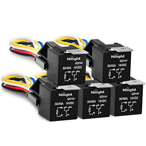
A relay fixes it completely: the switch carries a fraction of an amp to the relay coil, and the relay's contacts carry the real current on a short, heavy wire from the fuse block straight to the accessory. That is the entire concept, and it is why the relay kit is the first item on the list below rather than an afterthought.
The layout that works
Battery, then a main fuse or breaker within inches of the positive terminal, then heavy wire to a fuse block mounted somewhere dry and reachable. Each accessory gets its own fused circuit from that block to its relay, and each relay is triggered by its switch on the panel. Grounds go to clean bare metal, scraped and sealed, not to a painted bracket.
Then label everything. Not for elegance — for the day in two years when something stops working and you are trying to remember which of the six identical black wires goes to the rear light.
Choosing the parts
Fuse block: count your circuits, then add half again
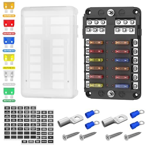
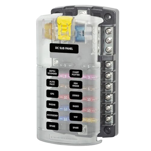
A block is cheap and rewiring is not. If you are installing three accessories, buy six circuits; if you are installing six, buy twelve. The other question is whether it has an integrated negative bus — that halves the wiring, because each accessory lands its positive and its ground in the same box instead of hunting for a chassis ground on the far side of the vehicle.
Relays: SPST or SPDT
A single-pole single-throw relay is a switch: on or off. A single-pole double-throw relay also gives you a normally-closed contact, which lets one relay switch one circuit on while switching another off. Buy SPDT and you have both options for the same money.
Crimps beat solder in a vehicle
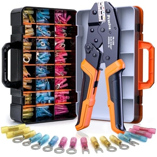
This is contested and it should not be. A properly executed crimp with an adhesive-lined heat-shrink connector is gas-tight, sealed and — critically — flexible. Solder wicks up the strands and creates a rigid section that becomes a stress riser, and a vehicle vibrates for a living. That is the failure I have actually seen: not a bad joint, a broken wire an inch from a perfect joint.
Use a ratcheting crimper. It will not release until the crimp is complete, which removes the most common error — stopping halfway because it felt tight enough.
Copper versus copper-clad aluminum
CCA wire is aluminum with a copper skin. It is cheaper and lighter, it has higher resistance than copper for the same gauge, and it needs to be sized up to carry the same current. It is fine for triggers and signal runs. It is the wrong choice for anything carrying real load, and it is more prone to corrosion at the one place twelve-volt circuits fail: the crimp.
Protect the run
Split loom over everything that crosses an edge, a grommet through every panel, and enough slack at each end that the wire is never the thing taking the strain. A wire chafed through on a sharp bracket is the most avoidable failure on this list and the most common.